DIY Heat Gun Coffee Roaster 2.0
In my first post, I showed the very basic heat gun roaster I built. After a couple roasts with it I knew I had to step my game up. So I give you version 2.0 of my flour sifter heat gun roaster.
Mechanics
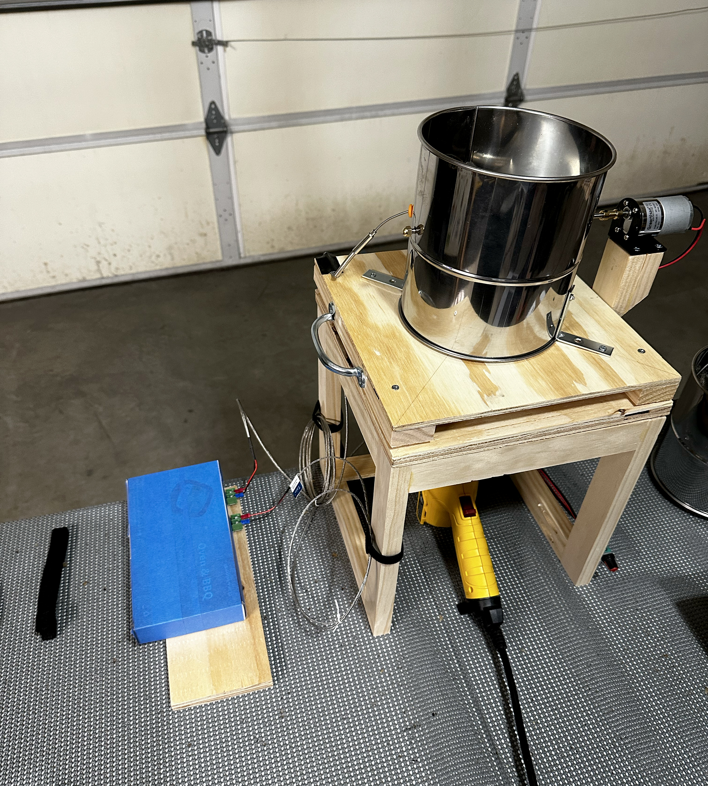
I wanted to add some features to help me automate things. First up was the mechanics of the roaster itself. I wanted a motor to drive the sifter, but using a power drill seemed a bit clunky to me, so I purchased a 120rpm DC motor, power supply, and PWM motor speed controller to drive the flour sifter action.
I also wanted to try and replace the stock flour sifter wire agitators with Larry Cotton’s famous wobble disk.
Bill of Materials (BOM)
- 8-cup flour sifter
- 12V 120 RPM DC Motor
- 12V Power Supply
- PWM Motor Speed Controller
- M5 200mm Threaded Rod
- 5mm to 6mm Brass Shaft Coupling
- 10mm OD/5MM ID Aluminum Tubing
- M5 Hex Locknuts
- 9 inch pizza pan (for cutting into a ~5 inch wobble disk)
Making the wobble disk
While I found lots of videos and photos online (almost too many), I had a hard time figuring out the actual build instructions for the wobble disk. So I figured I’d help (or add to the chaos) by posting my own instructions here.
The first thing to work out was the size of the disc. I first tried cutting several templates out of cardboard and fitting them into the flour sifter and trying to approximate the rotation and clearance.
I used a compass like this to measure against my cardboard template and draw my cut line on the pizza pan. You could also just trace your cardboard template. Mine ended up being just shy of about 5 inches in diameter and I still had to file it down a bit. The advise I read was to leave enough clearance between the flour sifter screen and the disk edge so that you can easily turn things by hand with beans inside. So I just filed down the edges of the disk until I found the sweet spot.
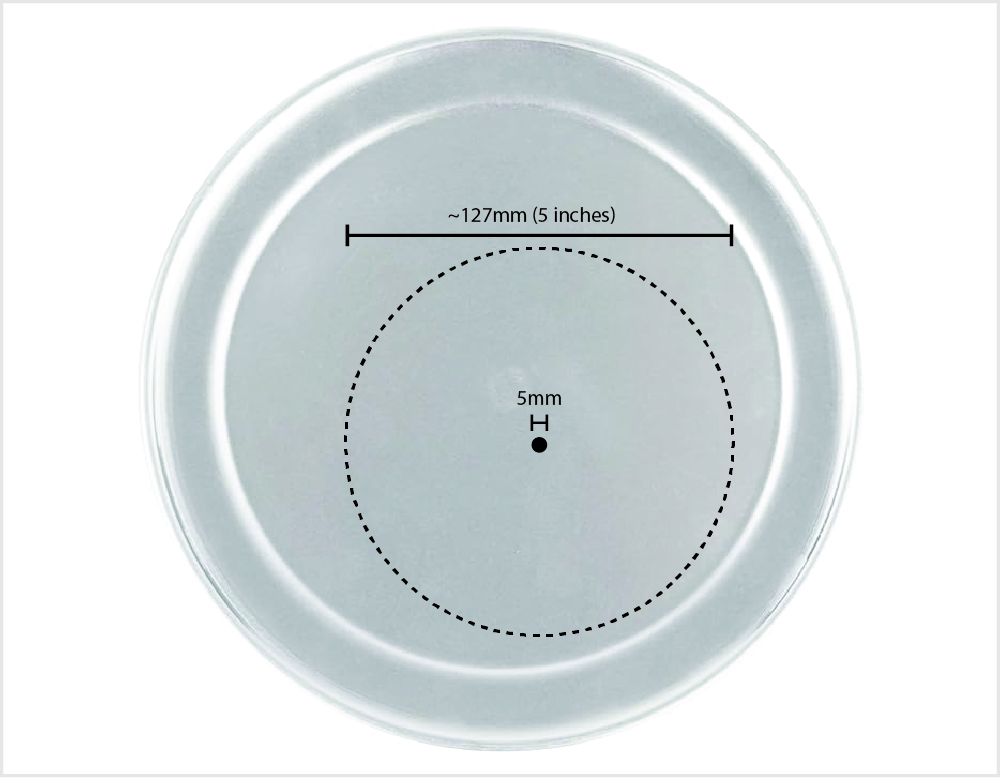
To cut the disk, I clamped the pizza pan down and used a jigsaw with a metal cutting blade to cut out the disc. I then drilled a ~5mm hole directly in the center. Using a power drill, I first drilled straight down to create the hole. Then as the drill was running, I tilted it at a 45 degree angle to create a grove for the disk to sit comfortably on the threaded rod at an angle.
Mounting the wobble disk
Next up was to cut the aluminum tubing, which will mount the disk onto the threaded rod. Start by drawing your first cut at a 45 degree angle, about 40mm from the end. This should create a piece of tubing a little over an inch long, with a 90 degree cut on the left end, and 45 degree cut on the right. Your second cut should be at a 90 degree angle about 40mm from the first 45 degree cut you made to create the other side.
Remove the existing rod and handle that came with the flour sifter, and replace it with the straight 200mm threaded rod. I kept and reused the end cap nut, which fit the new rod perfectly.
Here’s a top-view of what it should look like all fully assembled:
Electronics
Update: May 20, 2024: I ended up purchasing a Phidget thermocouple sensor and USB hub, which seems to work far better than the original MAX6675 sensors I used with the Raspberry Pi detailed below. While MAX6676 mostly worked, I was getting too much noise in the voltage readings. The Phidgets don’t seem to have any voltage issues.
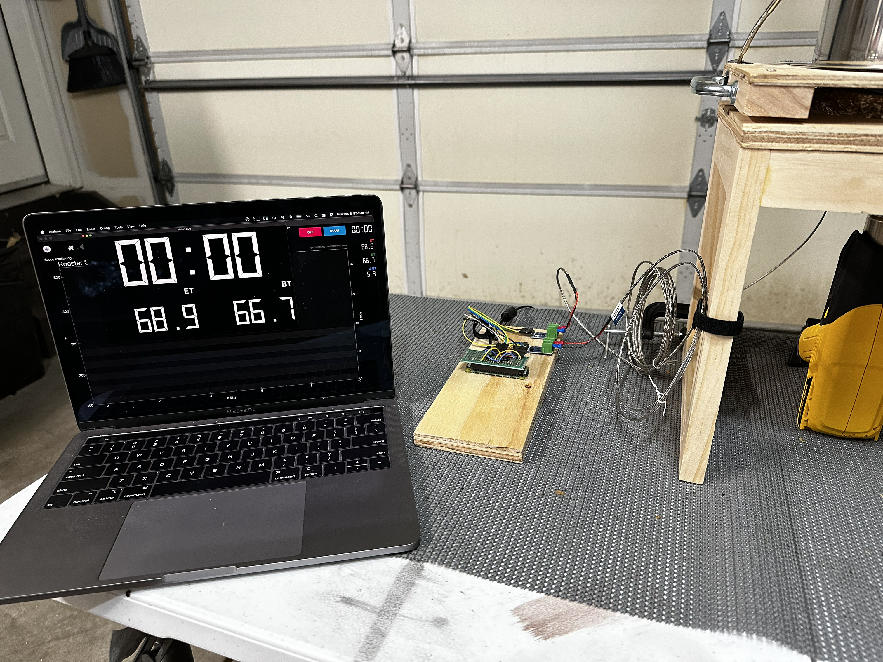
I decided I wanted to start tracking temperatures and using software like Artisan, like the pros do. So I decided I needed to add some thermocouples to measure both the bean and environment temperatures. An easy way to do this would be to buy a thermocouple meter like the ones listed on Artisan’s site. But who wants easy? I decided to build something using a Raspberry Pi I had laying around.
Bill of Materials (BOM)
- 100mm Flexible K-Type Thermocouple (bean temperature)
- 100mm K-Type Thermocouple (for environment temperature)
- MAX6675 Temperature Sensors
- Raspberry Pi Zero W
I’ve been using the Raspberry Pi for years. So I figured with a couple cheap MAX6675 thermocouple amplifiers, and some code, I could figure out how to forward some temperature readings on to Artisan.
First I needed to connect everything up on a breadboard. Here’s the wiring diagram I made for it.
You’ll notice the 3.3V, GND, SCK and CS pins are shared between multiple sensors. The SO pin will connect to it’s own pin on the RPI.
| MAX6675 | Raspberry Pi GPIO |
|---|---|
GND |
Pin 1 (Ground) |
VCC |
Pin 6 (3v3 Power) |
SCK |
Pin 18 (GPIO 24) |
CS |
Pin 7 (GPIO 4) |
SO |
Sensor 1: Pin 22 (GPIO 25) Sensor 2: Pin 32 (GPIO 12) |
TODO: I’ll eventually release my code and setup guide for reading the temperatures and connecting it all to Artisan. The basic gist of the code is that it takes temperature readings every 1 second, and provides an HTTP endpoint for getting the readings. From there I just have a local script on my laptop for connecting it to Artisan.
Once I had tested that everything was working, I decided to use a prototyping board and consolidate the wiring a bit and mounted things on a piece of scrap plywood (until I can print up a case for it).
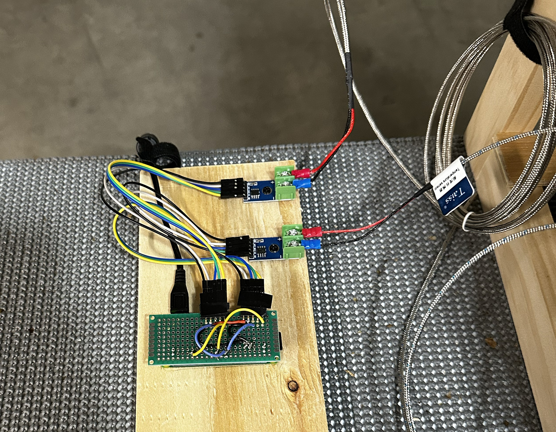
Additional Notes
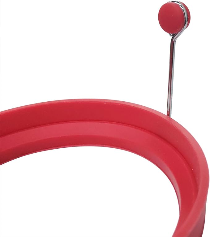
I had some initial issues with my thermocouples getting electrical interference from the DC motor connected to the flour sifter. Turns out this is a common problem with the MAX6675 thermocouple amplifier chips. Every time I would flip the motor on, the temperature would instantly drop. I found that I needed to better insulate the thermocouples from the flour sifter. I (mostly) solved this by adding a silicone plug to the hole in the flour sifter and then sticking the thermocouple through that. I ended up using a small piece of silicone from the handle of an extra egg ring mold I had lying around. It fit perfectly, and greatly reduced the interference.
But I think ultimately I’ll need to upgrade to a better, more accurate amplifier like the AD8495.